

THIN-FILM ELECTRICAL METROLOGY
Four-point probe: from four contacts to thin-film resistivity
A student guide to probe roles, the 4.532 factor, ohms per square and geometry limits. One calculation, checked step by step.
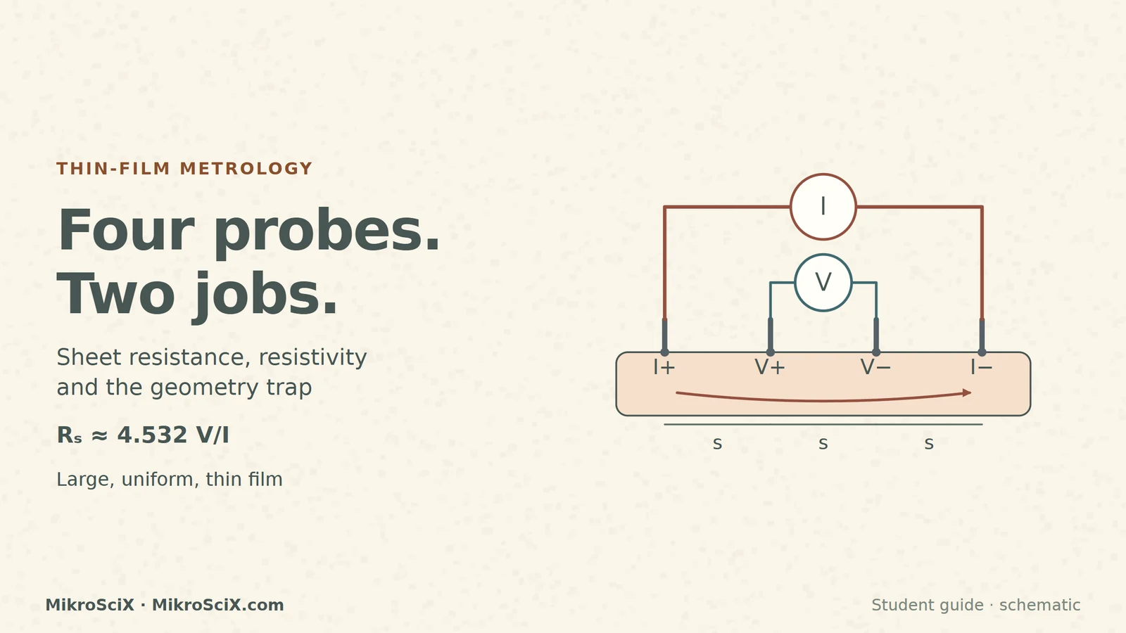
Four needles touch one film, yet the instrument gives two very different kinds of information: a current that you choose and a voltage that the film produces. The useful result is sheet resistance, written Rₛ and measured in ohms per square. It describes lateral conduction in a thin layer. To interpret it, you need to know what the probes do, why a geometric factor appears, and when the familiar formula stops applying.
This guide follows one illustrative calculation throughout: 1 mA through the outer probes, 10 mV between the inner probes, and a separately known film thickness of 100 nm. Those values are teaching inputs, not measurements of a named material or recommended instrument settings. The three sources below support the method; every worked number is our calculation from their relations.
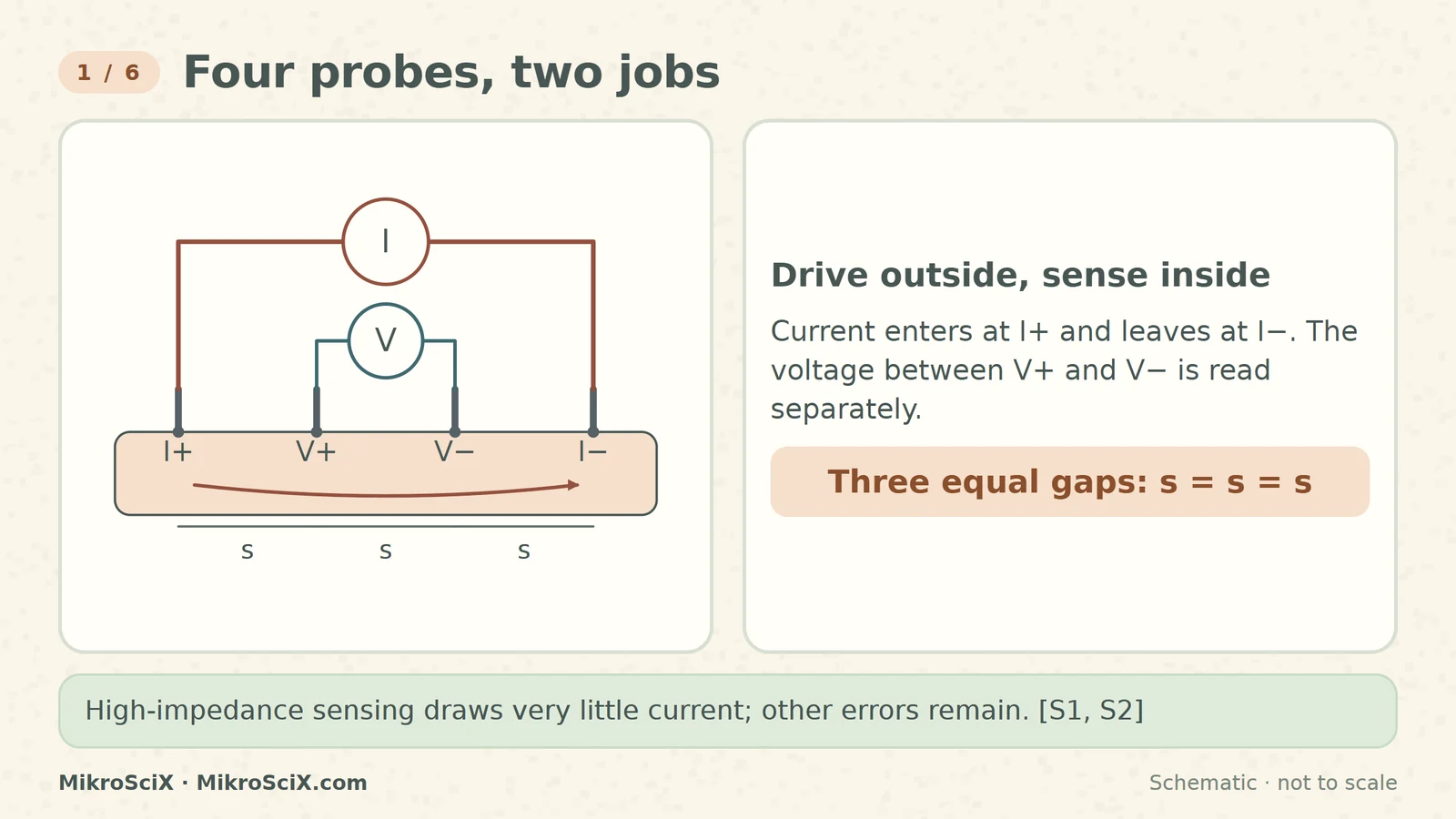
Put four small contacts on a straight line, separated by three equal gaps s. The current source injects conventional current at the first outer probe and collects it at the last. A voltmeter measures the potential difference between the two inner contacts. Those inner contacts touch the film, but the voltmeter has a high input impedance, so its current is negligible compared with the driven current. [S1, S2]
Check it yourself. Count the independent roles: two current contacts and two voltage contacts, not four current injectors. In a diagram, a current marker should enter the film through one outer lead and leave through the other. The inner leads need a voltage label, rather than a stream of moving charges.
What breaks. High input impedance suppresses voltage drops in the sensing leads and their contacts; it does not promise a perfect measurement. Contacts must be suitable for the measurement, the source must deliver its selected current, and the film must operate in the intended ohmic range. A good drawing preserves all four physical contacts instead of pretending contact resistance has ceased to exist. [S1, S3]
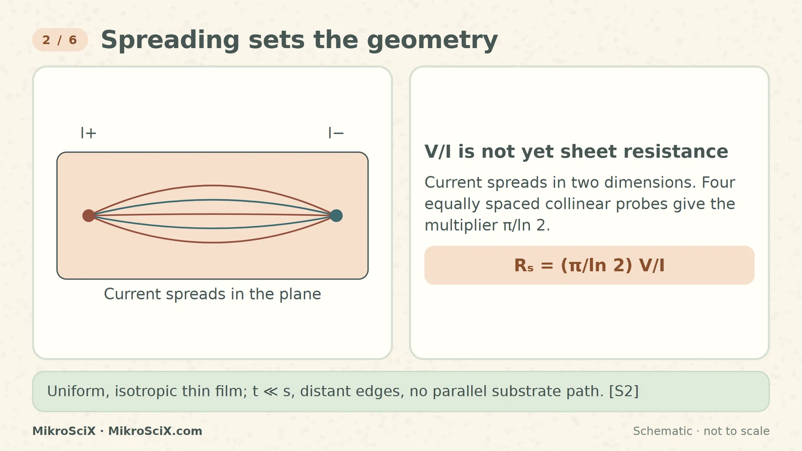
Current spreads sideways through the film. It does not travel along a narrow wire joining the four needles. TU Graz derives the thin-film potential from radial spreading around a source and a sink. For equal collinear spacing on an effectively infinite sheet, the result is V = I Rₛ ln(2)/π. Rearranging gives:
Rₛ = (π/ln 2) V/I ≈ 4.532 V/I.
Check it yourself. The multiplier π/ln 2 is approximately 4.53236. It is dimensionless. Therefore V/I supplies ohms, and the notation Ω/□ identifies the sheet interpretation. The factor is a consequence of the current geometry; it is not an empirical correction for bad contacts. [S2]
What breaks. This formula assumes a uniform, isotropic thin conducting layer. Its thickness t is much smaller than the probe spacing, the lateral boundaries are distant, and the substrate does not provide a parallel current path. A different four-terminal layout does not automatically inherit the same factor. In particular, this collinear arrangement is distinct from a van der Pauw pattern with perimeter contacts.
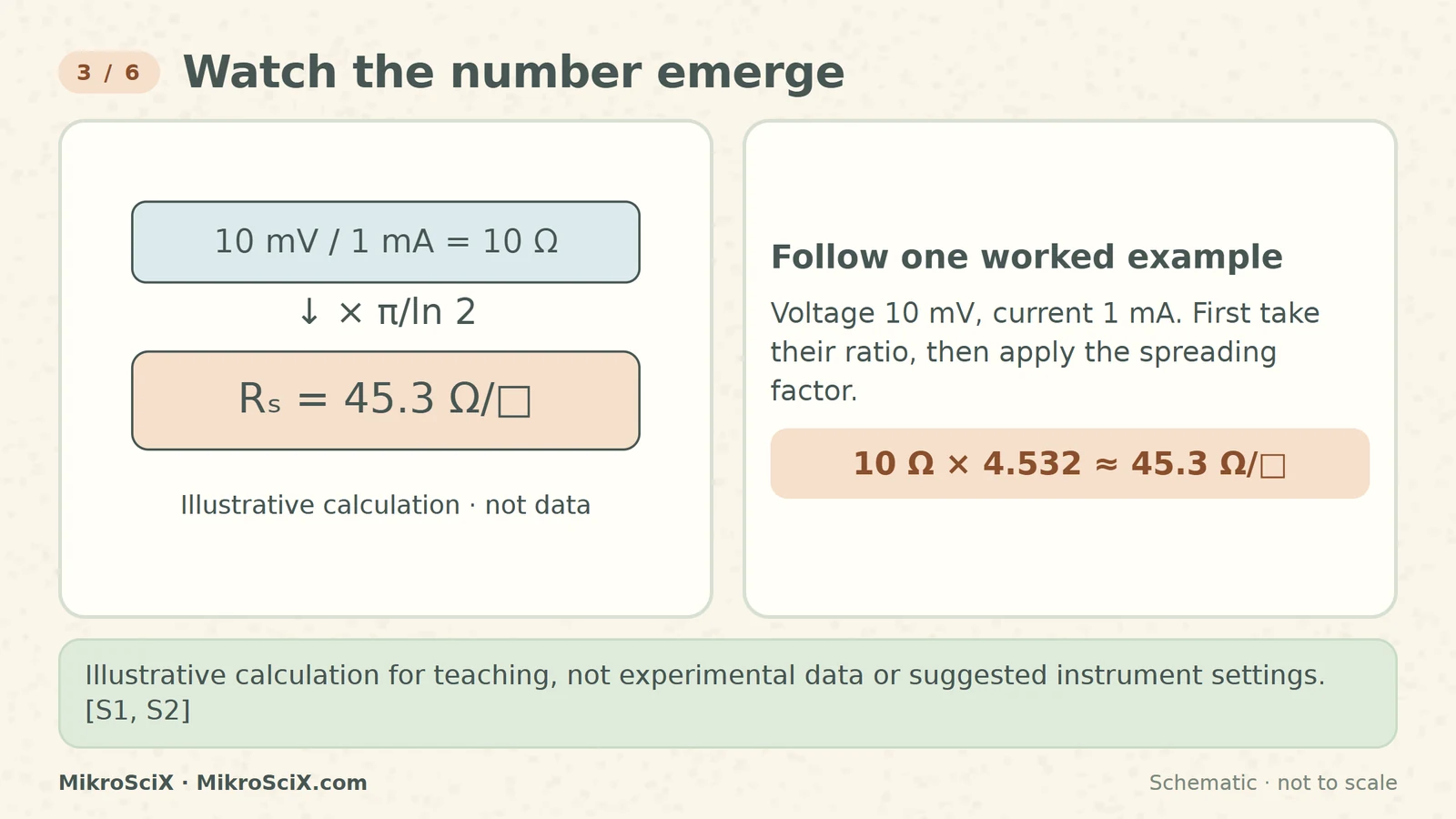
Our example drives I = 1 mA and reads V = 10 mV. First convert consistently: 1 mA = 0.001 A, and 10 mV = 0.010 V. Their ratio is 10 Ω. This is the measured four-terminal transfer resistance for this configuration; it is not the final sheet resistance.
Check it yourself. Rₛ = 4.53236 × (0.010/0.001) = 45.3236 Ω/□, displayed as 45.3 Ω/□. Keep the unrounded factor during the calculation and round the final displayed result. Using millivolts divided by milliamps also gives ohms because the two milli prefixes cancel.
What breaks. Units must describe the same measured quantities: the current through the outer pair and the voltage between the inner pair. A voltage measured somewhere else would correspond to another geometry. The convenient round inputs do not establish an uncertainty, a material identity or a safe current for every film. They only make the conversion visible.
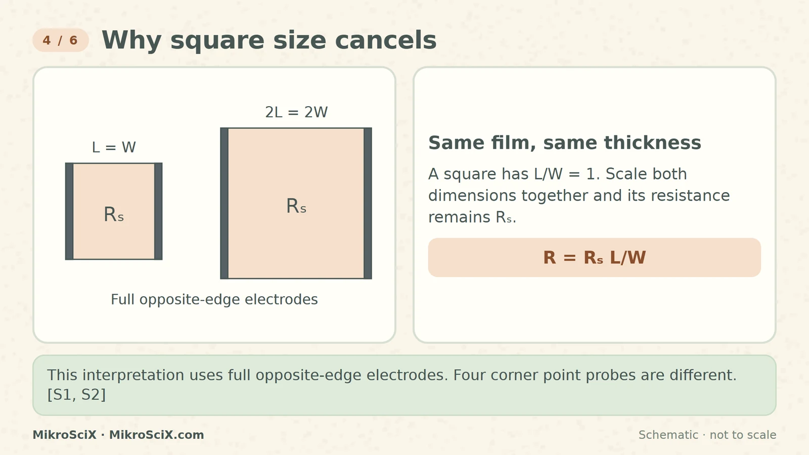
Imagine a separate rectangular strip of the same uniform film, with ideal electrodes covering two entire opposite edges. Its resistance is R = Rₛ L/W. This relation follows from ordinary resistance R = ρL/(tW), with Rₛ = ρ/t. For a square, L = W, so the length-to-width ratio is one. The square's size cancels. [S1, S2]
Check it yourself. A square with side a and a square with side 2a both have L/W = 1. At our example sheet resistance, each gives 45.3 Ω between full opposite edges. A rectangle with L = 2W gives about 90.6 Ω. That rectangle contains two squares in series along the current direction.
What breaks. Keep material, film thickness and temperature the same while changing the square size. Also keep full-edge contacts: four point contacts at the corners do not create the same current distribution. Ω/□ is not Ω per square metre, and a larger physical area is not automatically a lower resistance if length and width increase together.
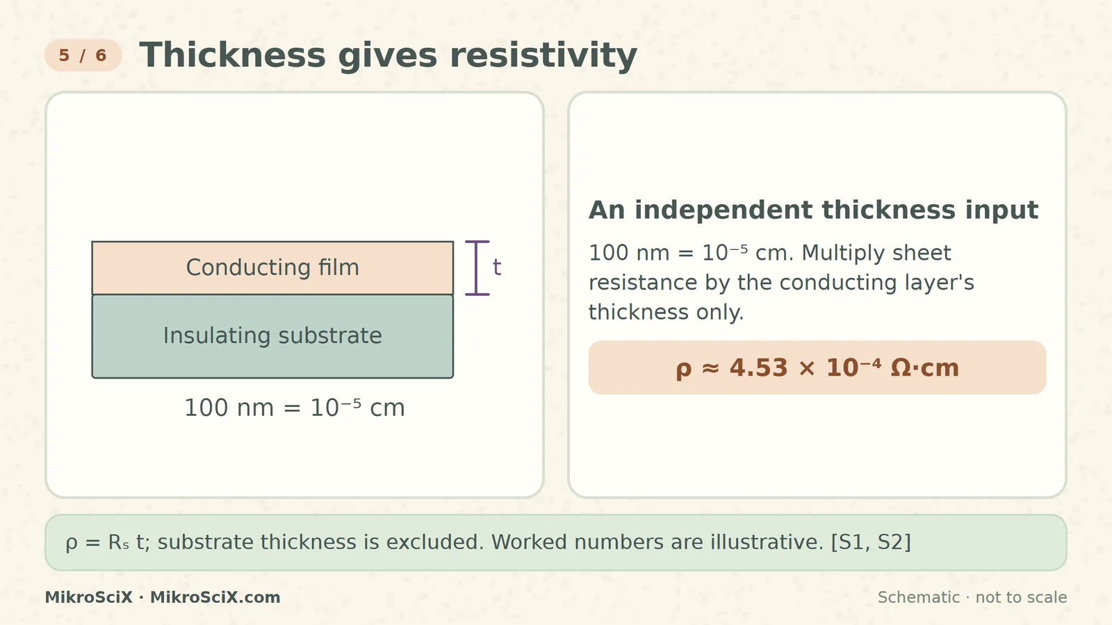
Sheet resistance combines the material's resistivity and the conducting layer's thickness. A thin layer of a given material offers less conducting cross-section than a thick layer. If the layer is uniform and its thickness is independently known, use ρ = Rₛ t. Sheet resistance alone cannot separate those two contributions. [S1, S2]
Check it yourself. Our independently supplied 100 nm equals 10⁻⁷ m or 10⁻⁵ cm. Multiplying the unrounded 45.3236 Ω/□ by 10⁻⁵ cm gives 4.53236 × 10⁻⁴ Ω·cm, displayed as 4.53 × 10⁻⁴ Ω·cm. In SI units the same result is 4.53 × 10⁻⁶ Ω·m. These are two unit conventions for one resistivity.
What breaks. The bracket for t must span only the conducting film, not the supporting substrate. Multiple conducting layers or a conducting substrate can add parallel paths. In that case a single-layer conversion may not describe the intended film. A separate thickness measurement is an additional input, not an output magically supplied by the four electrical probes.
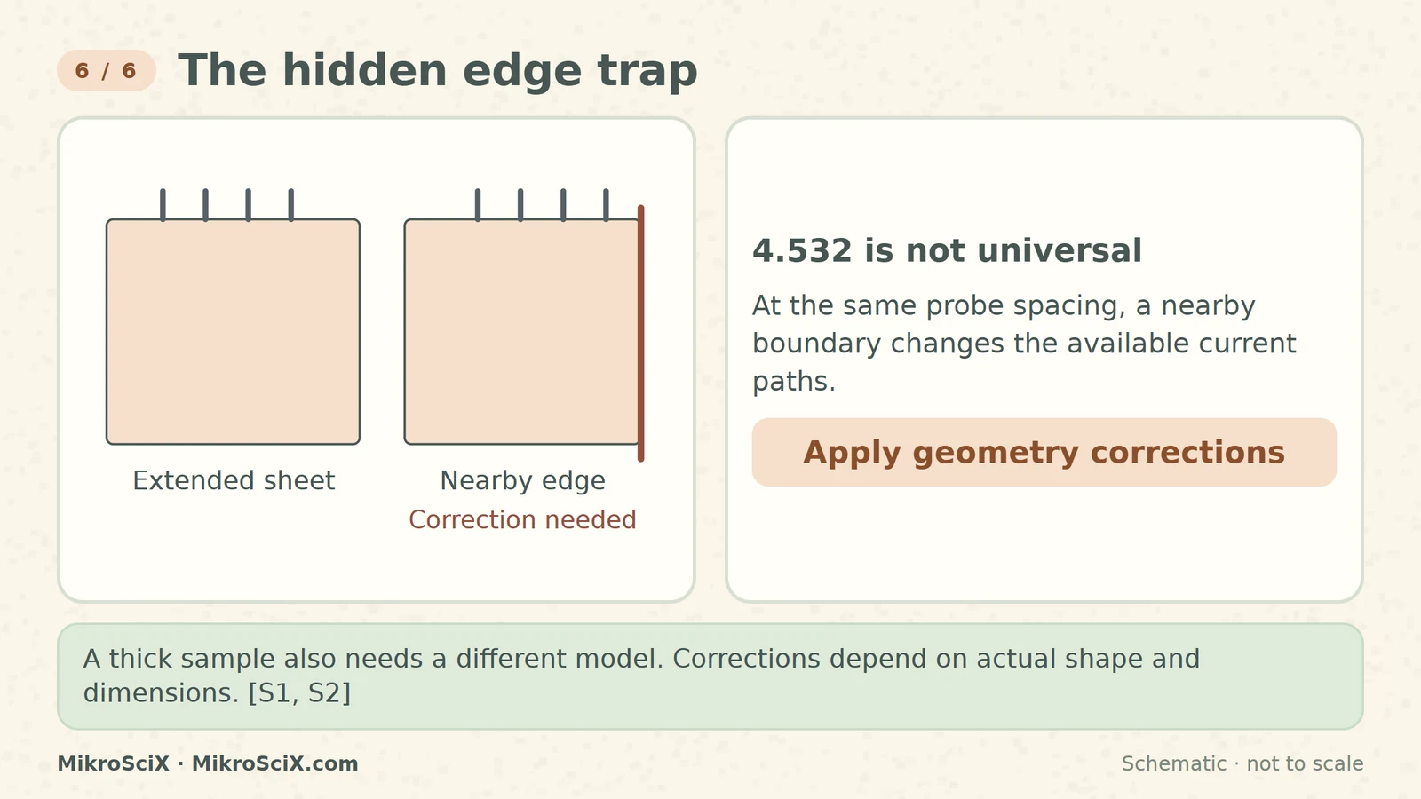
A nearby edge prevents current from spreading as it would on a large sheet. A sample that is thick relative to spacing also permits a different distribution through its depth. Illinois and TU Graz describe the need for boundary and thickness corrections. There is no one universal extra multiplier for every small, thick or oddly shaped sample. The correction depends on the actual geometry. [S1, S2]
Check it yourself. Before typing 4.532 into a spreadsheet, sketch four contacts and three equal gaps. Mark the film thickness, the closest boundaries and the possible substrate path. Decide whether the large, thin, single-layer assumptions are justified. If they are not, select an appropriate correction or measurement model before converting the voltage reading.
What breaks. Merely moving the probes away from one visible edge does not prove every boundary is remote. A schematic drawing can crop an extended sheet, so it should explicitly state that the drawn border is not the physical sample edge. Our diagrams use colour for higher and lower potential; their paths and coloured regions are explanatory, not measured field maps.
- The voltage becomes 20 mV when the current becomes 2 mA. Did the sheet resistance change?
- The same material is made twice as thick, while resistivity stays fixed. What happens to its sheet resistance?
- A full-edge-contact rectangle has L/W = 3 and Rₛ = 45.3 Ω/□. What is its ideal resistance?
Answers. (1) No: 20 mV/2 mA is still 10 Ω, so the ideal-sheet result remains 45.3 Ω/□. (2) Rₛ = ρ/t halves to about 22.7 Ω/□. (3) R = 3 × 45.3 = 135.9 Ω. Each answer keeps the model's conditions; none is a new measured result.
Separate current from voltage, identify the current geometry, and add independent thickness only when you need resistivity.
Watch the short
Videos don’t load automatically. The videos are hosted on YouTube. Allow YouTube once and every video on the site loads by itself; your choice is remembered. The articles never need consent.
Sources
- S1 · University of Illinois Urbana-Champaign, ECE 444 — Four Point Probe
- S2 · Graz University of Technology — Four point resistivity measurements
- S3 · Ossila — Calculate Sheet Resistance Using the Four-Probe Method
Schematic, not to scale. Worked numbers are illustrative calculations, not measured data. AI narration accompanies the video.